Cleairy logo. Products

Packed Bed Wet Scrubber – For Acidic & Alkaline Exhaust Gas Treatment

Packed Bed Wet Scrubber is a wet exhaust-gas treatment device that uses a Packing Layer to increase the gas–liquid contact area. After pollutant-containing gas enters the scrubber, it comes into full contact with the Circulating Spray Liquid on the Packing surface, allowing pollutants to transfer from the gas phase to the liquid phase through dissolution, Absorption, or chemical reaction. Depending on the nature of the pollutants, water, acidic solutions, alkaline solutions, or other specialized absorption liquids may be used.

This equipment is commonly used to treat HCl, HF, SO2, NH3, H2S, acidic and alkaline exhaust gases, and certain water-soluble or reactive gases, and is widely used in chemical processing, electroplating, pickling, electronics, wastewater treatment, laboratory exhaust ventilation, and other industrial exhaust-gas treatment systems.

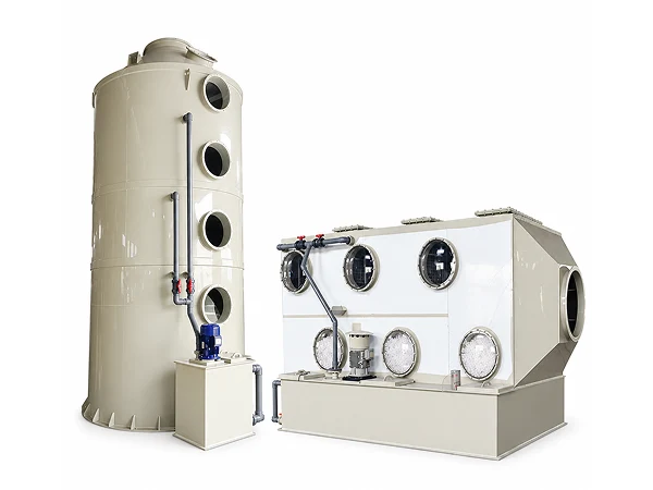
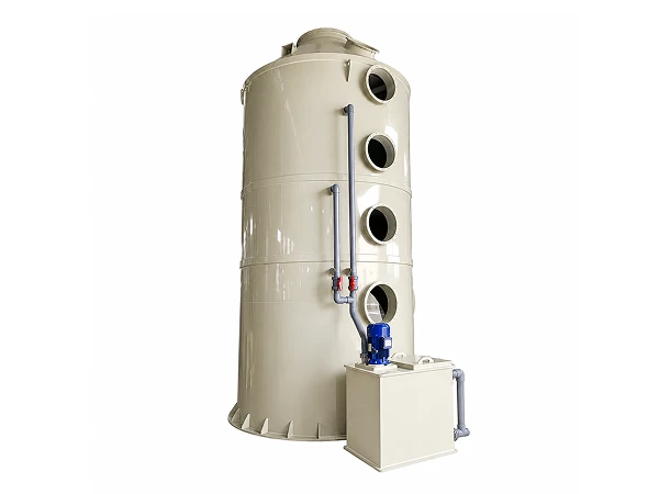
A packed bed wet scrubber placed on a flat surface
Features
  • Large gas–liquid contact area. The Packing Layer provides a large wetted surface area for the absorption liquid.
  • Suitable for a variety of absorbable gases. Different types of pollutants can be treated by selecting different scrubbing liquids.
  • Multiple system configurations available. Automatic chemical dosing and pH control, mist elimination, and other systems can be configured.
  • Multiple corrosion-resistant materials available. PP, FRP, and other materials are available.
  • Strong process adaptability. System parameters such as tower diameter, Packing height, and spray flow rate can be adjusted according to actual conditions.
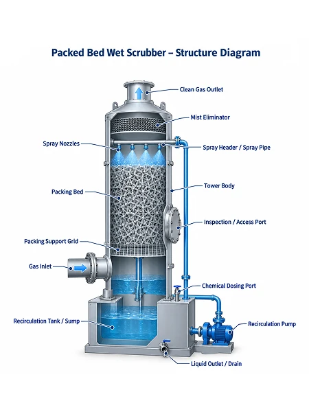
Structure diagram of the packed bed wet scrubber showing its main components
Structure

The packed bed wet scrubber mainly consists of the following components:

  • Scrubber Tower: Houses the Packing, Spray System, and Mist Eliminator, and provides space for gas–liquid contact.
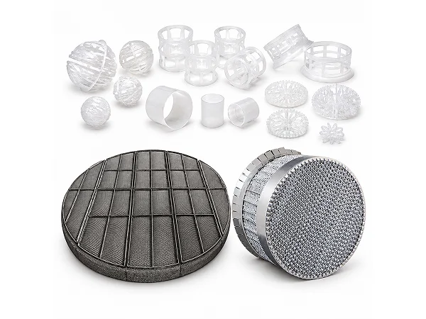
  • Packing Layer: The core gas–liquid mass-transfer zone of the scrubber.
  • Spray System: Consists of spray piping and nozzles, uniformly distributing the recirculating liquid over the top of the Packing Layer.
  • Mist Eliminator: Removes liquid droplets entrained in the treated gas.
  • Recirculation Tank: Stores and collects the scrubbing liquid.
  • Recirculation Pump: Recirculates the scrubbing liquid from the Recirculation Tank to the Spray System.
  • Chemical Dosing System: Adds different absorbents according to the type of gas being treated.
Principle
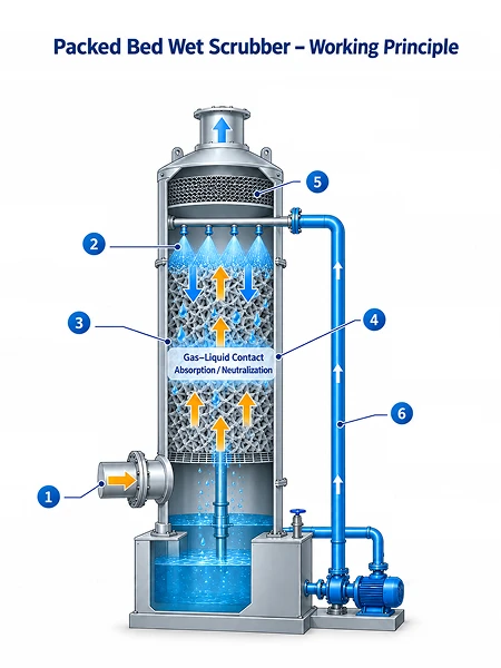
  1. Exhaust gas enters the scrubber. Pollutant-containing exhaust gas typically enters the lower section of the scrubber and flows upward through the packing.
  2. Scrubbing liquid enters the packing. The recirculation pump delivers the scrubbing liquid to the nozzles, which spray it downward from above the packing bed.
  3. Counter current gas–liquid contact is established. The liquid flows downward along the packing surfaces and forms a liquid film, while the exhaust gas flows upward.
  4. Pollutants are absorbed. Depending on their properties, pollutants are transferred from the exhaust gas to the scrubbing liquid through a series of reactions and are absorbed and neutralized.
  5. Mist is removed. The treated gas enters the mist eliminator at the top, where scrubbing liquid droplets entrained in the gas stream are separated.
  6. The recirculating scrubbing liquid is reused. The scrubbing liquid returns to the recirculation tank and continues to circulate after monitoring, chemical dosing, and water replenishment.
Working principle diagram of the packed bed wet scrubber: counter current gas-liquid contact in the packing layer
Specifications
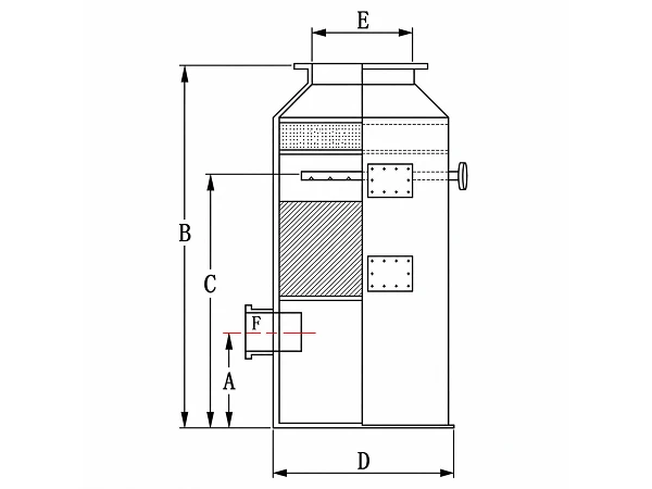
Dimension diagram of the packed bed wet scrubber with labels A to F
Table 1: Packed Bed Wet Scrubber Specifications
Model Airflow Capacity
(m/min)
A
(mm)
B
(mm)
C
(mm)
D
(mm)
E
(mm)
F
(mm)
Circulating Water Flow Rate
(L/min)
JPS-10 10 780 3590 2910 300 150 150 30
JPS-20 25 805 3690 2960 450 200 200 40
JPS-30 45 860 3915 3060 600 300 300 70
JPS-40 70 925 3965 3185 750 350 350 110
JPS-50 100 925 4015 3085 900 450 450 150
JPS-60 110 1125 4135 3155 1000 450 450 190
JPS-70 170 1175 4285 3255 1200 550 550 270
JPS-80 230 1225 4435 3355 1400 650 650 370
JPS-90 300 1275 4585 3455 1600 750 750 490
JPS-200 380 1100 4350 3125 1800 800 1300 × 400 600
JPS-300 470 1125 4430 3175 2000 900 1450 × 450 680
JPS-400 570 1125 4505 3175 2200 950 1600 × 450 770
JPS-500 680 1125 4555 3175 2400 1050 2400 × 450 922
JPS-600 800 1200 4755 3325 2600 1150 2000 × 600 1100
JPS-700 920 1200 4805 3325 2800 1250 2200 × 600 1260
JPS-800 1130 1200 4965 3345 3100 1350 2400 × 600 1540
Note: Special designs are available for sizes above Ø3100 upon request.
Related products